
Additional sizes may be available!
Additional sizes may be available! Email me when available
Overview
| * | Salinity probe module for all AquaController Apex controller systems |
| * | Expansion module provides conductivity & temperature probe ports |
| * | Monitor aquarium salinity in real-time from your computer or mobile device |
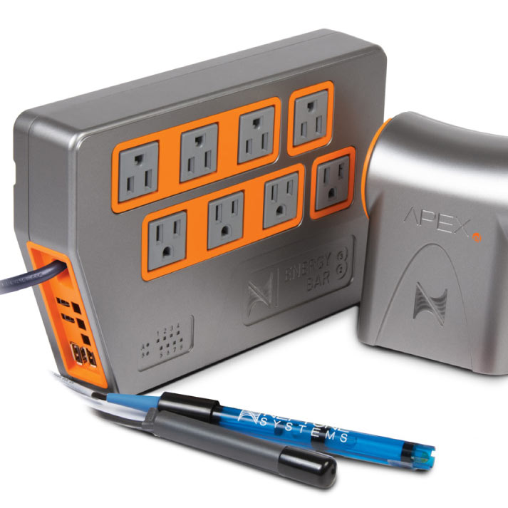
Monitor aquarium salinity in real-time with this simple upgrade to your AquaController Apex Controller System. Neptune Systems AquaController Apex PM2 Salinity Module expands the monitoring and control capabilities of your Apex system by adding conductivity and temperature probe ports. Six additional I/O switch inputs are great for ATO, feed buttons, float switches, water sensors, flow sensors and more!
Neptune Systems AquaController Apex PM2 Salinity Module is an invaluable expansion option for reef-keepers or any hobbyists with a saltwater aquarium. Provides 4 measurement ranges (0-900 µS/cm, 0-9.0 mS/cm, 0-90.0 mS/cm, 0-50 ppt) to suit hobbyist preference.
Connect a Neptune Systems AquaController Apex Temperature Probe (sold separately) to the additional temperature port on the PM2 Salinity Module and set the temperature compensation to experience the most accurate real-time salinity measurement possible!
Features
- Monitor/Control Conductivity/Salinity and temperature.
- 4 Measurement ranges (0-900 µS/cm, 0-9.0 mS/cm, 0-90.0 mS/cm, 0-50 ppt).
- 6 digital inputs for dry contact switches- float switches, push buttons, pressure sensors, etc.
- Full data logging support in Apex Base module.
- Up to 240 AquaBus modules can be added to the Apex system.
- Plug and Play. Automatically recognized when installed into the Apex system.
- Two AquaBus connectors for flexible expansion via AquaBus.
- Comes with 3 ft AquaBus cable.
- Galvanic Isolation for accurate and reliable probe readings.
- LED Status Indicator.
- Upgradeable firmware.
- Compatible with all Apex systems.
Physical Installation
WARNING: Your Apex Base Module must be running firmware version 4.02 or higher to support the Probe Module 2. The current firmware version can be checked from the Apex Display on the Self Test screen. If needed, please upgrade the Apex Base Module firmware to 4.02 or higher before proceeding with the installation. See the Apex Setup and Programming Guide for firmware upgrade instructions.
The AquaController Probe Module 2 should be securely mounted in a location free from moisture. Use wood screws through the mounting tabs of the probe module case or if mounting on drywall, use drywall anchors (mounting hardware not included).
- Mount all modules above the water line of the aquarium.
- Be sure to utilize drip loops on all power cords, AquaBus cables and probe cables.
WARNING: Water damage will void your warranty! Mount all modules in locations safe from moisture exposure.
Initial Connections
Plug one end of the included AquaBus cable into one of the AquaBus ports on the Probe Module and the other end into an available AquaBus port on your existing Apex system. It makes no difference which AquaBus port is used and you do not need to power down the system when connecting AquaBus accessories as the system is plug-and-play.
WARNING: NEVER plug standard USB devices into any AquaBus connector or AquaBus accessories into computer USB ports. Damage to the AquaBus accessory and/or USB device may result.
Connect the Conductivity Probe (must be purchased separately, available from your Neptune retailer) to the port labeled Conductivity on the Probe Module 2. Push the Mini-DIN connector into position paying close attention to the pin alignment.
If you are using a temperature probe with the Probe Module 2 (must be purchased separately, available from your Neptune retailer), plug in to the port labeled Temp on the Probe Module and place the other end of the Temperature Probe in the aquarium water in an area of medium to high flow in the same area as the conductivity probe.
Startup
As soon as the Probe Module is connected to an active AquaBus, the Probe Module will power up and begin to initialize. When first connected to an AquaController Base Module (through the AquaBus), the Probe Module will automatically be assigned an AquaBus address and be added to the AquaController configuration. The LED Status indicator on the Probe Module will flash yellow while it is being initialized. Once initialized, the LED Status indicator will be solid green. The LED Status indicator will flash yellow when the Probe Module is powered on and communication with the AquaController Base Module is lost.
Verify the Installation
Verify the probe module was initialized and added to the AquaController Apex configuration:
Apex Display: Setup > Module Setup > Modify Name - From this screen, you can see all AquaBus modules installed on the system.
Web Interface: Configuration> Module Setup - Verify the probe module is listed in the Apex Module List.
Update Probe Module Firmware
A new version of firmware for Probe Modules may be included with Apex Base Module firmware updates. You should check the firmware version status when the Probe Module is first installed and after updating the AquaController Base Module firmware. See the section titled Updating Firmware in the AquaController Apex Setup and Programming Guide for instructions to update AquaController Apex Base Module and probe module firmware.
To check or update an Apex module firmware:
Apex Display: Setup> Module Setup> Update Module - Use the Up/Down arrows to highlight the Apex module to update, push Select to update.
Web Interface: Configuration> Module Setup - In the Module Configure area, in the Module: box, select the Apex module to update from the dropdown list, click the Update Firmware radio button, click the Submit Module Update button, a new browser window will open to display the update status.
Conductivity Probe Setup
To enable the Conductivity Probe:
Apex Display: Setup> Cond Setup> Cond Enable - If you have more than one Conductivity port on your system, use the Up/Down arrow keys to choose the port you wish to configure, press Select, then use the Up/Down arrow keys to select ON/OFF for that port, press OK when done or Exit to discard changes.
Web Interface: This option is not available from the Web Interface.
Conductivity Range
The PM2 supports 4 conductivity ranges to support the conductivity measurement of various solutions. The four ranges are described in Table 1-Conductivity Range Options.
NOTE: When the conductivity range is in salinity mode, the probe is still actually reading the conductivity of the water. Since the ratio of ions in saltwater is very well defined, there is a direct correlation between the conductivity of the water and the salinity of the tank.
NOTE: If the conductivity range is changed, don't forget to update outlet programs that are based on the conductivity reading as the values will change with the change in range.
| Range | Units | Calibration Solution | Description |
| Low | 0 to 850 S/cm | 477 S/cm | Typically used to measure the purity of RO/DI water. |
| Medium | 0.00 to 8.50 mS/cm | Typically used to measure the conductivity of a freshwater tank. | |
| High | 0 to 85.0 mS/cm | 53.0 mS/cm | Typically used to measure the conductivity of a saltwater aquarium. |
| Salinity | 0 to 45.0 PPT | 53.0 mS/cm | Typically used to measure the salinity of a saltwater aquarium. |
Temperature Compensation
Conductivity measurements are temperature dependent. The degree to which temperature affects conductivity varies from solution to solution. Seawater typically has a temperature correction factor of 2.1 to 2.3 %/C. In order for the PM2 to automatically compensate for changes in conductivity as the temperature of the water changes, you must connect a temperature probe to the PM2 and set the temperature compensation as described below. The temperature probe connected to the Apex Base Module cannot be used for automatic temperature compensation on the PM2.
WARNING: Temperature compensation value MUST be set to 0.0 if no temperature probe is attached to the PM2.
To set the Temperature Compensation:
Apex Display: Setup> Cond Setup> Temp Comp - Use the Up/Down arrow keys to select the temperature compensation in %/C, press OK when done or Exit to discard changes.
Web Interface: This option is not available from the Web Interface
NOTE: Leave the Temperature Compensation set to 0.0 if you are not using temperature compensation or do not have a temperature probe attached to the PM2. Other temperature probes on the system cannot be used for temperature compensation of the conductivity probe.
Conductivity Probe Calibration
NOTE: Set the Conductivity Range and Temperature Compensation settings before calibrating the Conductivity Probe. See the previous section for instructions on setting these parameters.
To calibrate a Conductivity probe:
Apex Display: Setup> Cond Setup> Cond Calibrate
- If you have more than one Conductivity probe enabled on your system, use the Up/Down arrow keys to choose the probe you wish to calibrate, press Select.
- Remove the conductivity probe from the tank and dry it off. Wait for the numbers on the bottom of the LCD screen to stop changing. It does not matter what value is displayed only that it is not changing. When the display stops changing, press the select button.
- Use the Up and Down buttons to select the calibration solution. Press the select button when the correct value is displayed. See Table 1-Conductivity Range Options for the recommend calibration solution.
- Place the Conductivity probe into the calibration solution. Wait for the numbers on the bottom of the LCD screen to stop changing. When the display stops changing, press the select button.
- The conductivity probe should now be properly calibrated.
NOTE: Many conductivity calibration solutions do not have the same ionic composition as saltwater, so using a refractometer to measure the salinity of the calibration solution is not valid. For example, the Neptune 53.0 mS/cm conductivity calibration standard will not have a salinity of 35 PPT or a specific gravity of 1.0259.
Web Interface: This option is not available from the Web Interface.
Conductivity Probe Maintenance
Conductivity probes should be periodically cleaned for best performance. The period between cleanings is up to the user but typically, every 1-3 months is normal. To clean the probe, gently brush the sides and tip of the probe with a soft brush to remove any debris. Rinse the probe in tap water. Soaking the probe in acid (vinegar) or alkali (borax) solution to remove mineral deposits is not typically needed but can be used to try and bring back an old probe that has stopped working.
Switch Inputs
The PM2 has a Mini DIN8 connector for switch inputs labeled I/O. These inputs can be used for switches, float switches, water sensors, flow sensors, etc. Switch inputs connected to Probe Modules will be identified as Switchx3_2, Switchx5_3, etc. The first number in the switch name corresponds to the AquaBus address assigned to the probe module. The second number corresponds to the switch input number (1-6).
WARNING: Do not apply voltage to the switch inputs or damage to the AquaController Apex may occur.
Connect switches to the AquaController Apex by connecting one wire from the mechanical switch to the ground pin (pin 8), and the other wire from the switch to one of the six digital inputs (pin 1-6). Connections can be easily made using a Neptune I/O Breakout box available at your local Neptune Retailer. The breakout box features spring-loaded connectors to make connections easy without tools or soldering.
The Apex and accessory inputs are TTL level (5V) inputs with internal pull-up resistors. With nothing connected, the switch inputs will indicate OPEN (Logic 1-5V). When connected to Ground (Pin 8), the switch will indicate CLOSED (Logic 0-0V).
Switch Inputs are programmed using the If Switch command. For example, if you wanted to turn a pump on when a float switch closes, you would add this command to the pump outlet program:
If Switch1 CLOSED Then ON
See the section titled Appendix 3 -Programming Reference and Appendix 4-Advanced Programming Examples in the Apex Setup and Programming Guide for more information.
Programming
The Conductivity probe will be identified as "Condx3," "Condx4," etc in the Apex system. The number in the probe identifier corresponds to the AquaBus number assigned to the PM2.
If a temperature probe is connected to the PM2, it is identified as "Tmpx3", "Tmpx4", etc. with the same AquaBus number as the pH/ORP probe.
Switch inputs connected to probe modules will be identified as Switchx3_2, Switchx5_3, etc. The first number in the switch name corresponds to the AquaBus address assigned to the probe module. The second number corresponds to the switch input number (1-6).
NOTE: The conductivity reading can be added to the Apex Display and Web Interface Status Screens. See the section titled Display Setup in the Apex Setup and Programming Guide for more information.
The following are some valid program statements (assumes that probe module is installed and configured on AquaBus address 4).
If Tmpx4 > 80.0 Then ON
If Condx4 > 53.0 Then ON
If Switchx4_2 CLOSED Then OFF
Please see the Programming Outlets section of the Apex Setup and Programming Guide for more information on programming the AquaController Apex.